


 |


| Quantity: | |
|---|---|
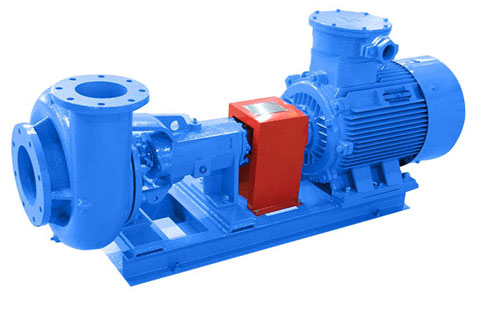


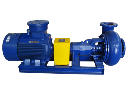
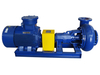
SB sand pump technical parameters
Model | Capacity (m3/h) | Head (m) | Efficiency (%) | [NPSH]r (m) | Power | |
Shaft (KW) | Motor (KW) | |||||
SB8×6×14 | 320 | 40 | 65 | 4.0 | 53.63 | 75 |
SB8×6×13 | 290 | 33 | 64 | 4.5 | 40.7 | 55 |
SB8×6×12 | 270 | 28 | 64 | 4.5 | 32 | 45 |
SB6×5×14 | 200 | 40 | 62 | 3.2 | 35.1 | 55 |
SB6×5×13 | 180 | 34 | 60 | 3.0 | 27.8 | 45 |
SB6×5×12 | 160 | 30 | 60 | 3.0 | 22 | 30 |
SB6×5×11 | 200 | 21 | 62 | 2.5 | 18.5 | 30 |
SB6×5×9 | 160 | 12 | 58 | 3.0 | 9.02 | 15 |
SB5×4×14 | 120 | 40 | 56 | 4.6 | 23.3 | 37 |
SB5×4×13 | 90 | 40 | 56 | 4.5 | 175 | 30 |
SB5×4×12 | 90 | 30 | 56 | 4.5 | 13.1 | 22 |
SB5×4×11 | 90 | 24 | 56 | 4.5 | 10.5 | 18.5 |
SB5×4×10 | 85 | 20 | 56 | 4.2 | 8.4 | 15 |
SB5×4×9 | 80 | 19.5 | 54 | 4.5 | 7.9 | 15 |
SB4×3×13 | 50 | 40 | 48 | 4.5 | 11.3 | 18.5 |
SB4×3×12 | 45 | 30 | 47 | 4 | 7.8 | 15 |
SB4×3×11 | 45 | 24 | 46 | 4 | 6.4 | 11 |
SB3×2×13 | 25 | 35 | 40 | 3 | 5.9 | 11 |
SB3×2×12 | 23 | 29 | 39 | 3 | 5.1 | 7.5 |
SB3×2×11 | 20 | 23 | 39 | 3 | 3.2 | 5.5 |
Common Faults and Troubleshooting of SB Sand Pumps
S/N | Fault | Cause | Troubleshooting |
1 | Excessive shaft power | 1. Friction between impeller and pump base end face/guard board/auxiliary impeller 2. Pump operates under a condition where head is much lower than that of the design point. 3. Excessively tight packing gland | 1. Adjust clearance between impeller and pump base end face to eliminate friction. 2. Check whether the service machine meets requirements; make opening of the drainage valve smaller, to make pump operates at the design point. 3. Loose the gland. |
2 | Reduced head and flow | 1. Large particles block suction pipe and impeller flow passage 2. Lower Speed of pump 3. Worn impeller 4. Excessive clearance between impeller and pump base end face, and increased leakage 5. Too small opening of inlet valve | 1. Eliminate tamper. 2. Make pump operates at the rated speed. 3. Replace impeller. 4.Adjust clearance between impeller and pump base end face. 5. Open inlet valve wider. |
3 | Bearing overheat | 1. Too much or little lubricant 2. Foreign substances in oil 3. Worn bearing | 1. Keep oil surface at position as specified by the oil level gauge. 2. Replace lubricant. 3. Replace bearing. |
4 | Vibration and abnormal noise produced during pump operation | 1.Unbalanced wearing of impeller 2. Worn bearing 3. Loose connection 4. Cavitation of pump | 1. Replace impeller. 2. Replace bearing. 3. Tighten all loose parts. 4. Improve suction condition, to prevent air into pump. |
5 | Serious leakage | 1. Seriously worn shaft sleeve. 2. Ineffective mechanical seal 3. Inconsistent inclined mouth of packing ring | 1. Replace shaft sleeve. 2. Replace mechanical seal. 3. Fill packing ring again as per requirements. |
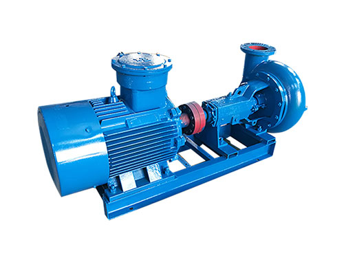


