Views: 0 Author: hmudcleaning Publish Time: 2023-04-19 Origin: Site
When using a drilling fluid separator, which steps are involved in the separation method?
1 Gravity separation
Gravity separation is determined by the difference in density between substances, the height of the liquid column, the size of the bubble, and the flow resistance inside the liquid. A simple drilling fluid tank or fracturing tank is a gravity separator that can store liquid, solid and gas until they are separated naturally. The gas rises and escapes from the top of the tank, and the oil separates from other fluids and floats to the top of the liquid. When the oil overflows the overflow or the built-in baffle of the tank, it is pumped away, and the drilling fluid and other fluids (such as salt water) are removed near the bottom of the tank. The solid phase settles at the bottom and stays there or is mixed into the liquid and then removed with conventional solid phase control equipment. Gravity separation is the most important method used in oil/water separation tanks and closed pressure separators.
2 centrifugal separation
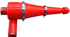
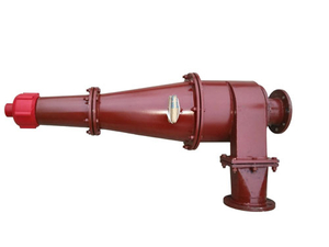
The drilling fluid is rotated by feeding it tangentially into a circular container or into a rotating cylindrical container. Oil, gas, water and solid particles are separated by artificial gravity generated by the centrifugal force of the rotating fluid. This method is used in many open or West texas separators, and involute spiral is often used in some closed pressure systems to produce gravity separation.
3 Impact, baffle and spray separation
The impact, baffle, and wine spray separation is to make the drilling fluid hit the baffle with a higher fluidity, thereby separating the gas. It can be separated directly from the drilling fluid discharged from the overflow pipe or chip removal pipe, or it can be separated after increasing the flow rate of the drilling fluid with a pump.
4 Parallel plate and film separation
Parallel plate or membrane separation is for the gas in the drilling fluid. The drilling fluid spreads out like a thin film on the parallel plates, making it easier for the gas to escape
(1) In the parallel plate separator, the gas-containing drilling fluid is pressurized between the two parallel plates, which makes the bubble distortion and deformation facilitate its rupture, which is common in commercial defogging and defoaming operations.
(2) Membrane separation is to allow the drilling fluid to flow on the plate in the form of a film, which causes the bubbles to expand and then burst. This thin film treatment is used in most vacuum degassing devices.
5.Vacuum separation
The vacuum degassing device is used to separate the gas mixed into the drilling fluid. It uses a reduced pressure (partial vacuum) to promote bubble expansion and rupture. This method is commonly used in degassing devices to remove the gas mixed into the drilling fluid.